
Solar Panel Installation Diagram PDF⁚ A Comprehensive Guide
This guide dives into the world of solar panel installation diagrams in PDF format. It’s designed to provide a comprehensive overview, helpful for both DIY enthusiasts and seasoned professionals in the solar energy sector.
Solar panel installation diagrams are essential tools for anyone involved in setting up photovoltaic (PV) systems. These diagrams, often available in PDF format, provide a visual representation of the entire installation process, from the placement of solar panels to the intricate wiring and electrical connections. They serve as a roadmap, guiding installers through each step and ensuring that the system is assembled correctly and safely.
These diagrams are not just simple illustrations; they are detailed technical documents that convey critical information. They show how different components of the solar system, such as solar panels, inverters, batteries, and charge controllers, are interconnected. They also specify the types of materials needed, the correct wiring gauges, and the necessary safety precautions. By following these diagrams, installers can minimize errors, reduce installation time, and ensure the long-term performance and reliability of the solar power system.
Whether you’re a homeowner embarking on a DIY solar project or a professional installer working on a large-scale commercial installation, having access to clear and accurate installation diagrams is paramount. These diagrams help to ensure that the system is installed in compliance with local regulations and industry best practices. They also play a crucial role in troubleshooting any issues that may arise during or after installation. In essence, solar panel installation diagrams are indispensable resources that contribute to the successful and safe deployment of solar energy systems.
With the increasing popularity of solar energy, the demand for skilled installers and reliable installation guides has grown significantly. Solar panel installation diagrams in PDF format are readily available online, offering a convenient and accessible way to learn and understand the intricacies of solar system installation. However, it’s important to choose diagrams from reputable sources and to verify their accuracy before using them. A well-designed diagram can save time, money, and potential headaches, while a poorly designed one can lead to costly mistakes and safety hazards. Therefore, investing time in finding and understanding the right diagram is a crucial step in any solar panel installation project.
Understanding the Basics of Solar Panel Systems

Before diving into the specifics of installation diagrams, it’s crucial to grasp the fundamental principles of solar panel systems. These systems convert sunlight into usable electricity through a process called the photovoltaic effect. Solar panels, also known as PV modules, are composed of numerous solar cells made from semiconductor materials, typically silicon. When sunlight strikes these cells, it excites electrons, creating an electric current.
A typical solar panel system consists of several key components working in harmony. The solar panels themselves generate direct current (DC) electricity. This DC electricity then flows to an inverter, which converts it into alternating current (AC) electricity, the standard form of electricity used in homes and businesses. The AC electricity can then be used to power appliances, lighting, and other electrical devices. Any excess electricity generated by the solar panels can be fed back into the grid, allowing the system owner to receive credits or payments from the utility company, a process known as net metering.
In addition to solar panels and inverters, a solar panel system may also include other components such as batteries for energy storage, charge controllers to regulate the flow of electricity to and from the batteries, and monitoring systems to track the system’s performance. The configuration and complexity of a solar panel system can vary depending on the specific application and the energy needs of the user. For example, an off-grid system, which is not connected to the utility grid, will typically require batteries and a charge controller, while a grid-tied system may not.
Understanding these basic principles is essential for interpreting and utilizing solar panel installation diagrams effectively. The diagrams illustrate how these components are interconnected and how the system as a whole functions. They also provide information on the proper sizing and selection of components, as well as the necessary safety measures to ensure the safe and efficient operation of the system. By having a solid understanding of the fundamentals, installers can better troubleshoot any issues that may arise during installation and ensure the long-term reliability of the solar panel system.
Key Components Shown in Installation Diagrams
Solar panel installation diagrams are visual representations of the entire solar energy system, detailing the placement and connection of each component. Understanding the symbols and representations used in these diagrams is crucial for successful installation. These diagrams typically highlight several key components, each playing a vital role in the system’s operation.
Solar Panels (PV Modules)⁚ These are the fundamental building blocks of the system, depicted as rectangles or squares with specific electrical characteristics (voltage, current, power). The diagrams indicate how the panels are arranged in strings (series connections) and arrays (parallel connections) to achieve the desired voltage and current output.
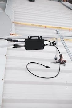
Inverter⁚ The inverter, often represented as a box with input and output terminals, converts the DC electricity generated by the panels into AC electricity suitable for household use or grid connection. The diagram specifies the inverter’s location and its connection to the panels and the electrical panel.
Combiner Box⁚ In larger systems with multiple strings of solar panels, a combiner box consolidates the wiring from these strings into fewer, larger conductors before connecting to the inverter. This simplifies wiring and provides overcurrent protection for each string.
Disconnect Switches⁚ These switches, depicted with specific symbols, allow for the isolation of different parts of the system for maintenance or emergency purposes. Diagrams show the location of AC and DC disconnects, ensuring safe operation and troubleshooting.
Wiring and Conductors⁚ Lines representing wires and conductors connect the various components. The diagram specifies the wire gauge (thickness) and type (e.g., THHN, USE-2) to ensure proper current carrying capacity and safety.
Grounding Equipment⁚ Grounding is crucial for safety, protecting against electrical shock and surge events. Diagrams show grounding conductors connecting the panels, inverter, and other components to a grounding electrode.
Mounting Hardware⁚ While not always explicitly detailed, the diagram may indicate the type of mounting system used (e.g., roof mounts, ground mounts) and their attachment points;
Metering Equipment⁚ For grid-tied systems, the diagram may show the location of the utility meter, which measures the amount of electricity consumed from and fed back into the grid.
By carefully examining the installation diagram, installers can determine the correct placement, wiring, and grounding of each component, ensuring a safe and efficient solar panel system. The diagram serves as a roadmap for the entire installation process.
Safety Precautions and Guidelines
Installing solar panels involves working with electricity, heights, and potentially hazardous materials. Therefore, adhering to strict safety precautions and guidelines is paramount to prevent accidents, injuries, and damage to equipment. Before commencing any installation work, thoroughly review the solar panel installation diagram PDF and understand all safety-related instructions.
Electrical Safety⁚ Always disconnect the AC power supply before working on any electrical components. Use appropriate personal protective equipment (PPE) such as insulated gloves, safety glasses, and non-conductive footwear. Never work on electrical components in wet or damp conditions; Verify that all wiring is properly insulated and connected according to the diagram.
Height Safety⁚ When working on rooftops, use appropriate fall protection equipment, including harnesses, lifelines, and guardrails. Ensure that ladders are securely positioned and in good working order. Be aware of weather conditions, such as wind or rain, that could increase the risk of falls. Avoid working alone; always have a spotter present.
Tool Safety⁚ Use tools that are in good condition and appropriate for the task at hand. Follow the manufacturer’s instructions for operating power tools. Wear safety glasses to protect your eyes from flying debris. Keep tools clean and properly stored when not in use.
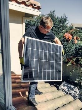
Handling Solar Panels⁚ Solar panels can be heavy and fragile. Use proper lifting techniques to avoid back injuries. Wear gloves to protect your hands from sharp edges. Avoid dropping or striking the panels, as this can cause damage. Cover the panels with opaque material during wiring to halt electricity production and prevent shocks.
Weather Conditions⁚ Avoid installing solar panels during inclement weather, such as rain, snow, or high winds. These conditions can increase the risk of accidents and make it difficult to work safely. Check the weather forecast before starting work and postpone the installation if necessary.
Permitting and Inspections⁚ Obtain all necessary permits and approvals before starting the installation. Contact your local building department or a qualified solar installer to determine the specific requirements in your area. Schedule inspections at appropriate stages of the installation to ensure compliance with safety codes and regulations.
Grounding⁚ Ensure proper grounding of all system components to protect against electrical shock and surge events. Follow the grounding instructions in the installation diagram and local electrical codes.
Professional Guidance⁚ If you are not comfortable performing any aspect of the installation, seek guidance from a qualified solar installer. They can provide expert advice and ensure that the installation is done safely and correctly.
By adhering to these safety precautions and guidelines, you can minimize the risk of accidents and ensure a safe and successful solar panel installation.
Step-by-Step Installation Process
Installing solar panels is a multi-stage process that requires careful planning and execution. The following step-by-step guide provides a general overview of the installation process. However, always refer to the specific solar panel installation diagram PDF and manufacturer’s instructions for detailed guidance.
Site Assessment and Planning⁚ Determine the optimal location for the solar panels based on sunlight exposure, roof orientation, and shading. Assess the roof’s structural integrity to ensure it can support the weight of the panels. Obtain necessary permits and approvals.
Mounting System Installation⁚ Install the racking system according to the manufacturer’s instructions. Ensure that the racking is securely attached to the roof structure using appropriate fasteners. Consider the local wind and snow load requirements.
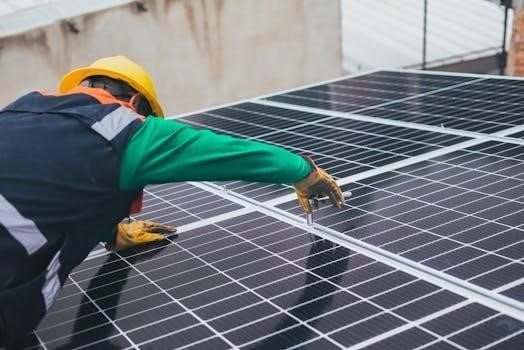
Panel Placement and Attachment⁚ Carefully lift and position the solar panels onto the racking system. Securely attach the panels to the racking using clamps or bolts. Ensure that the panels are aligned and spaced according to the installation diagram.
Wiring and Electrical Connections⁚ Connect the solar panels in series or parallel according to the system design. Use appropriate wiring and connectors that are rated for outdoor use. Ensure that all connections are tight and secure.
Inverter Installation⁚ Mount the inverter in a suitable location, typically near the main electrical panel. Connect the DC wires from the solar panels to the inverter. Connect the AC output of the inverter to the electrical panel.
Grounding⁚ Ground all system components according to the installation diagram and local electrical codes. Use appropriate grounding hardware and conductors.
System Testing and Commissioning⁚ After completing the installation, thoroughly test the system to ensure that it is functioning properly. Verify that the panels are producing power and that the inverter is operating correctly. Monitor the system performance over time to identify any potential issues.
Inspection⁚ Schedule a final inspection with your local building department to ensure that the installation meets all safety codes and regulations.
Detailed Breakdown of Steps⁚
- Racking Installation⁚ Measure and mark the locations for the racking system. Attach mounting brackets to the roof rafters using lag bolts or other appropriate fasteners. Install the rails onto the mounting brackets.
- Wiring⁚ Connect the positive terminal of one panel to the negative terminal of the next panel in series. Use MC4 connectors to ensure a secure and weatherproof connection. Run the DC wires from the panels to the combiner box.
- Inverter Connection⁚ Connect the DC wires from the combiner box to the inverter. Connect the AC output of the inverter to a dedicated circuit breaker in the electrical panel.
Remember to consult the solar panel installation diagram PDF and manufacturer’s instructions for specific details and requirements related to your system;
Roof Mounting Techniques Explained
Securing solar panels to a roof requires careful consideration of various factors, including roof type, local climate conditions, and building codes. Several roof mounting techniques are available, each with its own advantages and disadvantages. The solar panel installation diagram PDF often provides specific recommendations for mounting techniques based on the chosen system and roof type.
Flush Mounting⁚ This is one of the most common mounting techniques, where the solar panels are installed close to the roof surface. Flush mounting offers a clean, aesthetically pleasing appearance and is suitable for most roof types. Racking systems designed for flush mounting typically use rails that are attached to the roof rafters or trusses.
Railed Mounting⁚ This technique involves attaching rails to the roof and then securing the solar panels to the rails. Railed mounting provides greater flexibility in panel placement and allows for easier adjustments. It’s often used on roofs with uneven surfaces or when a specific panel layout is desired.
Rail-less Mounting⁚ Rail-less mounting systems eliminate the need for traditional rails, reducing the amount of material required and simplifying the installation process. These systems typically use clamps that attach directly to the roof mounting brackets.
Tilt Mounting⁚ Tilt mounting involves raising the solar panels at an angle to optimize sunlight exposure. This technique is particularly useful on flat roofs or roofs with unfavorable orientations. Tilt mounting systems can be adjusted to maximize energy production throughout the year.
Ground Mounting⁚ Although not directly on the roof, ground mounting is an alternative when roof space is limited or unsuitable. Ground-mounted systems can be positioned at the optimal angle and orientation for maximum sunlight exposure.
Integrated Mounting⁚ Integrated mounting solutions incorporate the solar panels directly into the roof structure, creating a seamless appearance. These systems are often used in new construction or roof replacement projects.
Detailed Explanation of Techniques⁚
- Flush Mounting⁚ Brackets are attached directly to the roof rafters, and rails are then attached to the brackets. The solar panels are clamped to the rails.
- Railed Mounting⁚ Similar to flush mounting, but the rails are raised slightly above the roof surface to allow for better ventilation and wire management.
- Rail-less Mounting⁚ Clamps attach directly to the mounting brackets, eliminating the need for rails. This reduces the overall weight and cost of the system.
- Tilt Mounting⁚ Adjustable frames are used to tilt the solar panels at the desired angle. This can significantly increase energy production, especially in winter months.
- Ground Mounting⁚ A framework is constructed on the ground to support the solar panels. This allows for optimal positioning and easy maintenance.
When choosing a roof mounting technique, consider the following factors⁚ roof type, roof pitch, local climate conditions, building codes, and aesthetic preferences. Always consult with a qualified solar installer to determine the best mounting solution for your specific situation. The solar panel installation diagram PDF is your go-to resource for specific system requirements.
Wiring and Electrical Connections
Proper wiring and electrical connections are crucial for the safe and efficient operation of a solar panel system. The solar panel installation diagram PDF provides detailed schematics and instructions for connecting the various components, including solar panels, inverters, batteries (if applicable), and the electrical grid.
Series vs. Parallel Connections⁚ Solar panels can be connected in series or parallel configurations, depending on the desired voltage and current output. In a series connection, the voltage of each panel is added together, while the current remains the same. In a parallel connection, the current of each panel is added together, while the voltage remains the same.
String Sizing⁚ String sizing refers to the number of solar panels connected in series. The string size must be carefully calculated to ensure that the voltage and current are within the operating range of the inverter. The solar panel installation diagram PDF typically includes a string sizing calculator or table.
Wiring Gauges and Conductors⁚ The correct wiring gauge must be used to handle the current flowing through the system. Undersized wires can overheat and cause a fire hazard. The solar panel installation diagram PDF specifies the appropriate wiring gauges for different circuit sections.
Overcurrent Protection⁚ Overcurrent protection devices, such as fuses and circuit breakers, are essential for protecting the system from damage due to short circuits or overloads. These devices should be installed in accordance with local electrical codes.
Grounding⁚ Proper grounding is crucial for safety and to prevent electrical shock. All metal components of the solar panel system, including the panels, racking system, and inverter, must be grounded to a common grounding point.
Disconnect Switches⁚ Disconnect switches allow the system to be safely isolated for maintenance or repairs. Both AC and DC disconnect switches should be installed.
Inverter Connections⁚ The inverter converts the DC electricity generated by the solar panels into AC electricity that can be used by household appliances or fed back into the grid. The inverter must be properly connected to the solar panels and the electrical grid.
Detailed Explanation of Connections⁚
- Series Connection⁚ Connect the positive terminal of one panel to the negative terminal of the next panel. Continue this process until all panels in the string are connected.
- Parallel Connection⁚ Connect all the positive terminals of the panels together and all the negative terminals together.
- Grounding⁚ Connect a grounding wire from the grounding lug on the solar panel to the grounding electrode.
- Inverter Connection⁚ Connect the DC output of the solar panels to the DC input of the inverter. Connect the AC output of the inverter to the electrical panel.
Always follow the wiring diagrams and instructions provided in the solar panel installation diagram PDF. If you are not comfortable working with electricity, hire a qualified electrician to perform the wiring and electrical connections.